Description of the Mill Machinery
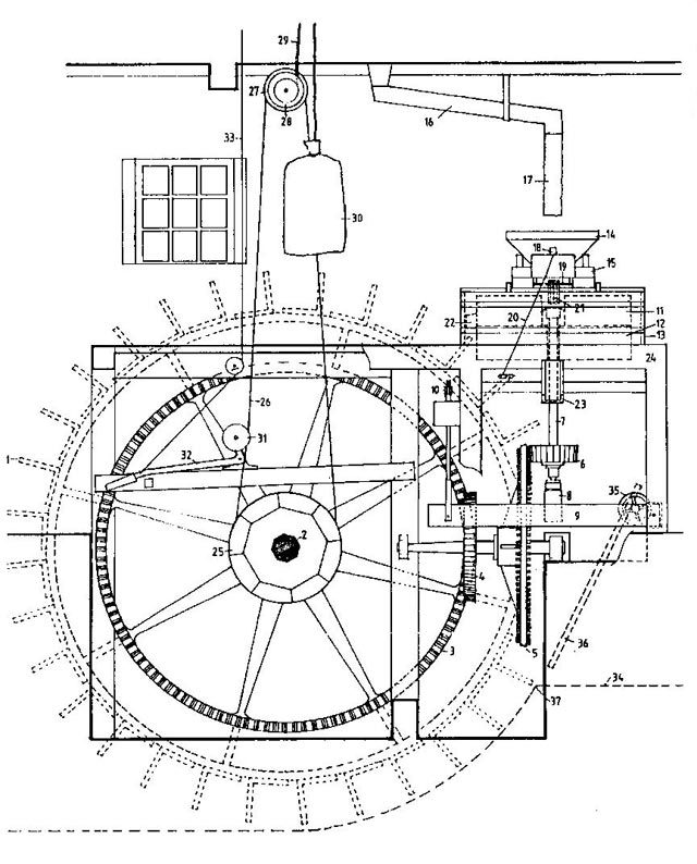
The waterwheel (1) has 32 oak or elm paddles and is mounted on an iron axle-tree (2) which passes into the building, where it supports the 10ft diameter cast
iron pit wheel (3). This meshes with the wallower (4), which is mounted on the same horizontal axle as the spur wheel (5), with its 96 cherry-wood
teeth. This, in turn, drives the stone-nut (6), through which passes the vertical spindle (7) that powers the grinding mechanism. The spindle bearing is supported by
the bridge-tree (8), the end of which is notched over the tentering arm (9), which is positioned by the tentering adjuster (10) to set the clearance
between the upper running stone (11) (supported and turned by the spindle) and the lower, fixed bedstone(12), between which the grain is ground. The two stones are
enclosed in a circular tun (13), surmounted by a hopper (14), that sits on a horse (15).
From the bins in the roof space, grain is fed through a feed chute (16) and canvas feed tube (17) into the hopper. From here it passes to the stones through the
feed control (18) by way of a vibrating shoe (19) with its control cord (20), agitated by a damsel (21) as it falls between the
stones. After grinding, the milled flour is directed by a scraper (22) fixed to the running stone to a flour chute (23), from which it is collected, via a coarse
vibrating sieve to separate the chaff/bran, in bags. The whole assembly is mounted on a sturdy oak hurst frame (24).
The main axle tree also carries a sack hoist drive wheel (25), which by means of a belt (26) and drive pulley (27), rotates the sack hoist
drum (28). This has a chain (29) running over a pulley at the apex of the roof, which raises the sacks of grain (30) to the storage bins above. The belt is
engaged when required by means of a jockey pulley (31) operated by a lever (32) raised from either the hurst frame or the floor above by a control cord
(33).
The speed of the waterwheel is governed by the rate of flow in the head race (34) which feeds it. Operation of a sluice control (35), which positions the
sluice (36), governs the flow of water to the invert (37) at the point where it strikes the paddles.
Gear ratios:
Pit wheel : Wallower = 120 / 35
Spur wheel : Stone nut = 96 / 22
Waterwheel : running stone = 120 / 35 x 96 / 22 = 15 (approx).
Therefore for each turn of the waterwheel the running stone turns about 15 times. So if the waterwheel is turning at 5 rpm the stone is rotating at about 75 rpm.